![]()
User Help
- User Help Home Page
-
 Quickstart User Guides
-
 Data Workflow User Guides
-
More Workflow User Guides
-
Other OMERO Applications
-
More

Using Scripts
Introduction
As well as scripts for exporting images and figures, OMERO.insight and OMERO.web also include a scripts menu for additional scripts. OMERO comes with some scripts pre-installed, to add functionality such as the Populate Metadata (under the ‘import_scripts’ item in the menu) and ‘utility scripts’. Custom scripts can be installed on the server by the system administrator so they are available to all users. For details see the scripts documentation page.
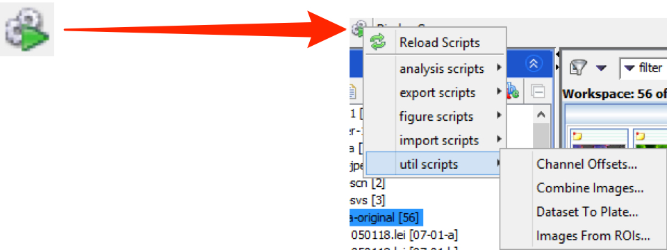
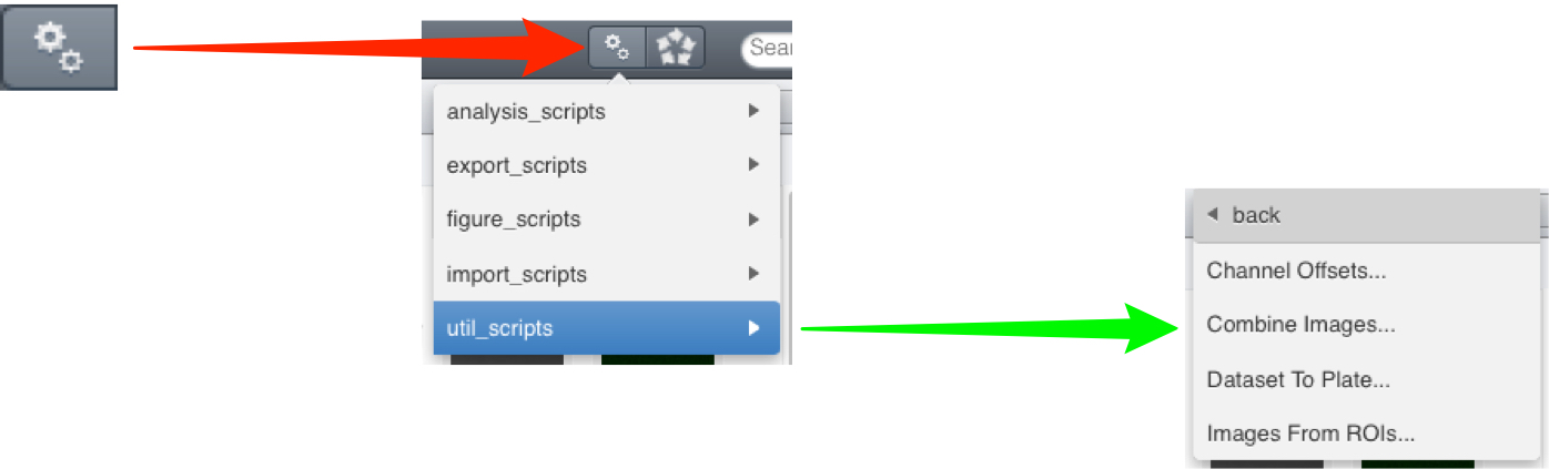
Click on the Scripts menu button and select the script to be run from the sub-menu.
OMERO.insight:
OMERO.web:

Populate Metadata Script
The Populate Metadata script allows the upload of metadata or analysis results associated with High Content Screening (HCS) data.
The metadata to be uploaded must be in Comma Separated Values format (.csv) with a line of entries for each Well in a Plate. The data in the .csv must be formatted appropriately, depending on whether it is being used to populate a Screen or a Plate with metadata (see below).
Detailed guidelines can be seen on the scripts documentation page.
Example metadata files for a Screen, populateMetadata_example_screen.csv, and a Plate, populateMetadata_example_plate.csv, can be downloaded from the OME resources page.
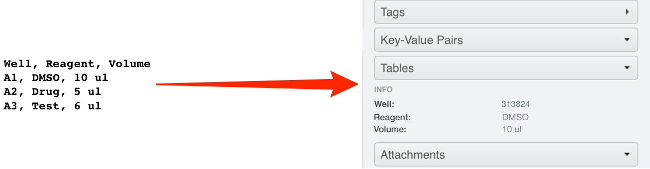
The column headers from the .csv become the row titles and the values in each row are read from the row in the .csv corresponding with that Well.
To illustrate, a .csv file with the contents shown would give a Table on Well A1 as follows (viewed in OMERO.web):
Populating a Plate with Metadata or Analysis Results
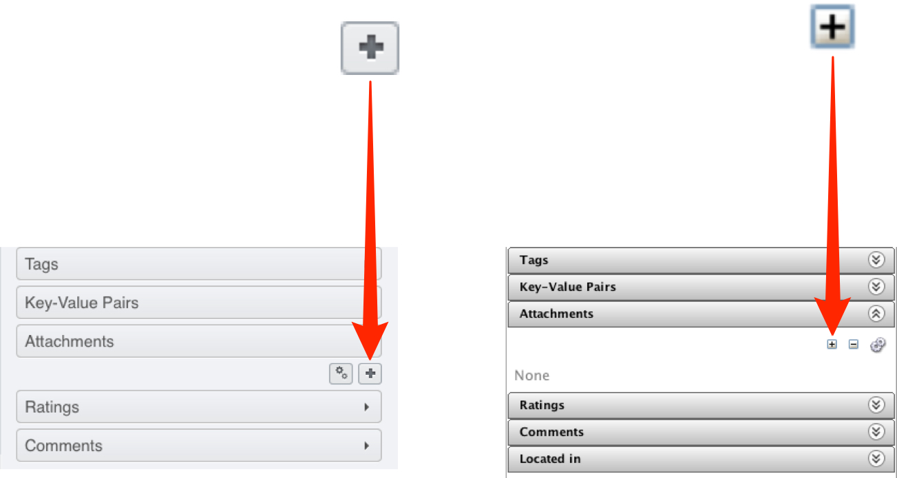
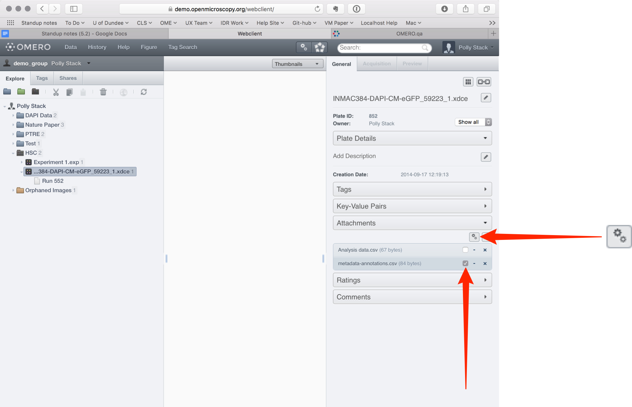
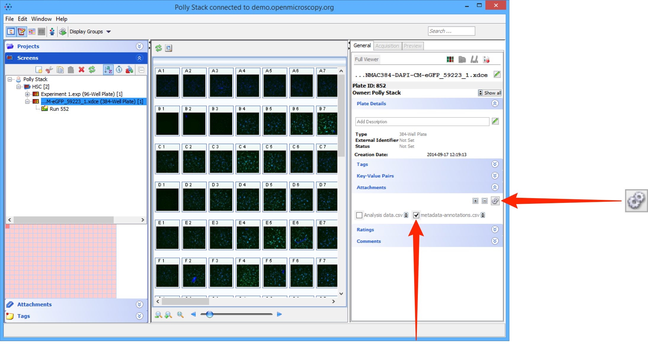
Select the Screen or Plate and attach the metadata .csv file to it using the + button under the Attachments tab.
If there is more than one .csv file attached to the Screen or Plate, click on the Select for Script button above the attachments.
Check the checkbox on the .csv attachment containing the metadata to be imported.
OMERO.web
OMERO.insight
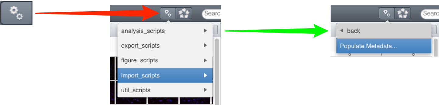
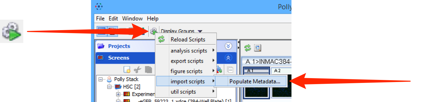
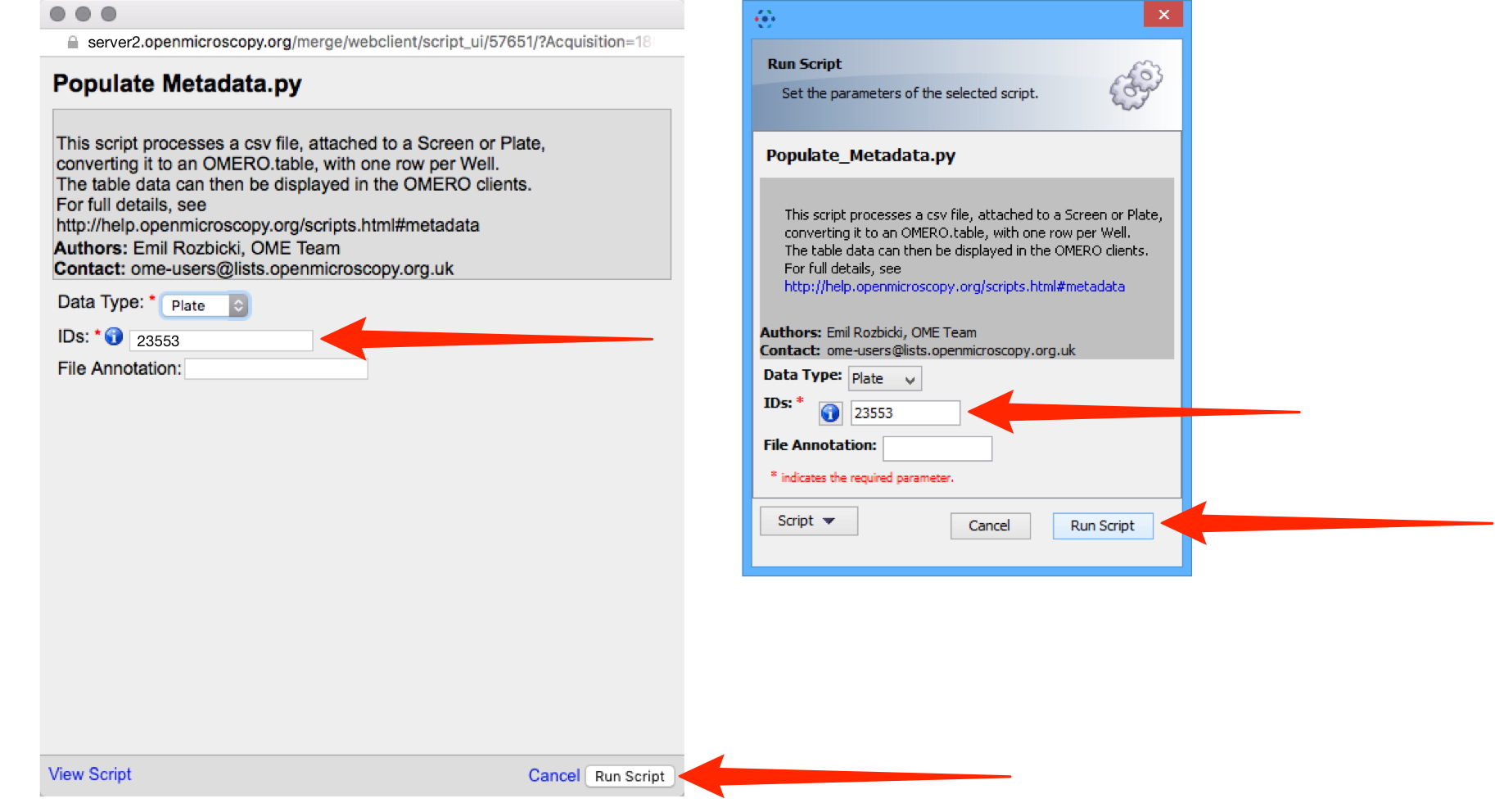
Click on the Scripts menu button and select import_scripts > Populate Metadata.
OMERO.web
OMERO.insight
In the Populate Metadata script window the ID number of the selected Screen or Plate should be in the IDs text box.
Click Run Script.
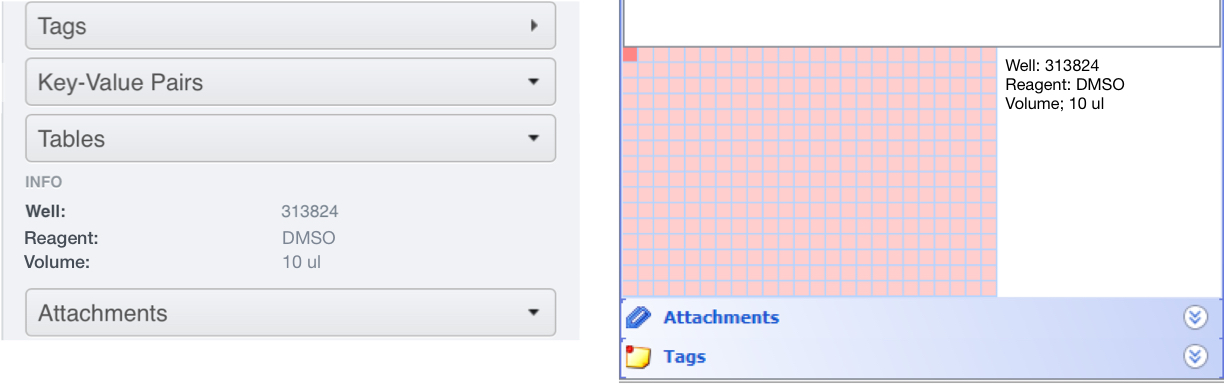
When the script has run, in OMERO.web, click on the Tables accordion tab in the right-hand General pane to view the metadata attached to each Well.
In OMERO.insight the table is shown next to the Plate map at the bottom of the Screens tab in the left-hand pane.
Note
A file called bulk_annotations will be attached to the Screen or Plate the script was run against. This is the OMERO.table file (PyTable) that contains the annotations for the Wells. This attachment must not be removed or deleted unless you want to remove all the annotations..
Populating a Screen with Metadata or Analysis Results
This is exactly the same procedure as described for the Plate above, but the metadata .cvs file is attached to a Screen and then used by the script.
If metadata is to be added to several or all Plates in a Screen then a column with the Plate name should be included in the .csv and the metadata will be attached to the Screen.
If metadata is to be added to a single Plate, then the Plate name column can be omitted, and the metadata will be attached to the Plate the metadata .cvs file is attached to when the script is run.
Utility Scripts
Channel offsets
The Channel Offsets script allows you to apply X, Y and Z offsets to individual channels in an image, creating a new image in the process. You can pick which of the channels from the source image to combine in the new image (up to the first 4 channels). The script can process several images at once, placing the new images in the same Dataset as the source images by default, or in a new Dataset if the “New Dataset Name” parameter is filled out.
Dataset to Plate
This script allows you to create a “Plate” from an ordered set of images in a Dataset, assigning images to a row and column based on their sequence by name. You can arrange images by row or column, choose the size of the row or column and how they are named.
View the movie above to see a demonstration of this script.
Combine images
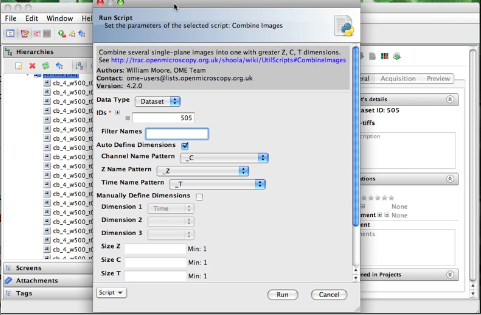
MOVIE: Combine Images demo. Slightly older movie here.
This script takes a number of single-plane images or image Z-stacks, identified either by Image_ID or by the ID of the Dataset that contains them. All input images should have the same X, Y and Z dimensions and are expected to have a single channel and time-point. If you want to use a subset of the images, choose the “Filter Names” option by entering some text. Only image names that contain this text will be used.
There are 2 alternative methods you can use to define which images are assigned to which Z, T or C index in the new image and how big the new dimensions are (see below).
Optionally you can specify colors and names for the channels in the new image.
Auto define dimensions
This option is chosen by default. This method uses the names of each image to try and identify the Z, T or C index. The user should choose the naming pattern for each dimension. For example, if you want to combine images named like these:
- image001_C01_Z01.tiff
- image001_C01_Z02.tiff
you should choose: * Channel Name Pattern: “_C” * Z Name Pattern: “_Z” * Time Name Pattern: “None” (optional)
If the input images are Z stacks, then the ‘Z Name Pattern’ will be ignored and the Z-size of the first image will be used instead.
Note
It is assumed that all images have the same Z size.
Manually define dimensions
With this option, the images are combined in the same order that they appear when sorted alphabetically (default in OMERO.insight). If you want to stitch the planes in a single dimension (e.g. time) then you only need to choose “Time” as the Dimension 1 value and this will do the job.
If you want to stitch the planes across 2 or more dimensions, you need to specify the dimensions in the order that they change in the list of input images. For example, images named like this:
- image001_C01_Z01.tiff
- image001_C01_Z02.tiff
- image001_C01_Z03.tiff
- image001_C01-Z04.tiff
- image001_C01-Z05.tiff
- image001_C02-Z01.tiff
- image001_C02-Z02.tiff
- image001_C02-Z03.tiff
- image001_C02-Z04.tiff
- image001_C02-Z05.tiff
The first dimension to change is Z (changes between images 1,2,3,4,5 in the list) and the second dimension to change is Channel (changes between images 5 and 6).
You must specify the Dimensions that these images represent in the combined image, in the order that they change in the sorted list. In the above example, Dimension_1 would be “Z”, since this changes first, and Dimension_2 is “Channel”. It is also necessary to specify the Size of the dimensions. In this case, “size Z” is 5 and “size C” is 2. It is possible to omit the size of the last dimension since this can be calculated by the script.
If the input images are Z stacks, you do not need to specify a Z dimension (it will be ignored if you do).
All Tutorial Material is available on line at: help.openmicroscopy.org
The Main OME website is at: www.openmicroscopy.org